If you have any interest in electronics hobby work, you are likely aware that the ultimate tool for analyzing signals and performing troubleshooting is an oscilloscope. These powerful devices are able to display a visual representation of a digital or analog signal. They are able to display the precise shape of a waveform, accurately indicate its voltage and frequency, spot distortion, “ringing” and other abberations. However, because these devices operate using a precision time base and microprocessor, they are often quite expensive tools to purchase. Purchasing a new oscilloscope can be a godsend, but can also break the bank. Older oscilloscopes can be of great value, but purchasing one that is in working order can be a challenge. This is not to mention the need for calibration and possible repairs. With the low cost of desktop and laptop computers, which may be sitting around collecting dust, why not use these machines to simulate the components in an oscilloscope? This can be accomplished with what is often referred to as a “PC based oscilloscope.”
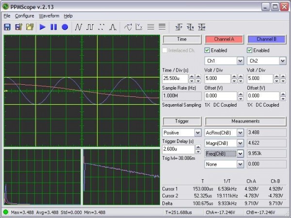
A PC based oscilloscope works by attaching a specialized device to any free USB port. This device, which is far less expensive than a full oscilloscope, provides one or more inputs, typically on BNC connectors. When combined with specialized software, a window displayed on the computer monitor takes the place of an oscilloscope’s built in CRT or LCD display. Rather than utilizing a custom microprocessor, the computer’s is used to perform signal analysis and measurement. This window displays all of the same information that would be found on a traditional oscilloscope. The signal can be displayed with variable “voltage per division” and “seconds per division,” thus allowing you to display multiple cycles with sufficient amplitude for a stable measurement. On USB devices with more than one input channel, two or more signals can be viewed at once in a different color. This makes comparing attributes of a signal very easy. One particularly useful application is placing a standard signal, such as the output from an oscillator, to an unknown signal. This can allow for lining up and in effect “calibrating” the unknown one.
Depending upon the model of USB interface device, it is possible to measure a wide range of voltages and frequencies. Most are able to measure up to one million samples per second in a single reading. Others are able to perform multiple readings, thus allowing for measurements as high as 20 million cycles per second. This is the equivalent of 20 megahertz. Models are available that are intended for reading logical voltage levels at 5 volts and below, or higher voltages, such as those encountered in AC line current. Higher end models contain multiple ranges, thus supporting the broadest range of signals.
A feature unique to this approach to signal analysis, is that a “snapshot” of the signal can be captured at any time. Some software packages are also able to record statistics of a changing signal. The resulting data can be used to form a report or generate a graph.
These capabilities, normally only found on the most expensive oscilloscopes, can be had for a remarkably low price. This is because you are leveraging capabilities of your old computer that you may not have known existed. It is even possible to connect a printer to capture signal images. Visual representations of signals can be stored as multimedia files by using off the shelf video capture software.
For more advanced electronics hobbyists, or those who wish to keep costs as low as possible, a USB interface can be built using just a handful of parts. These parts are available from local electronics retailers and specialized online catalogs. Not only is this an economical choice, it allows for a more customized design. Only the voltage and frequency ranges that are needed are implemented. Furthermore, the hobbyist can elect to install only as many input channels as he or she needs. The device can be attached externally and mounted in a project box, or even integrated into the computer on an expansion card bracket. When using the latter approach, the board can be connected directly to the motherboard using one of the included USB headers. These are available on most motherboards that are less than 10 years old.
These are just some of the benefits afforded by a quality PC based Oscilloscope. Whether you decide to purchase a pre-built unit or assemble your own, you will have a useful tool that will serve you for many years to come.


